Install and Purge Nozzle
Install Nozzle on Nozzle Assembly
Note
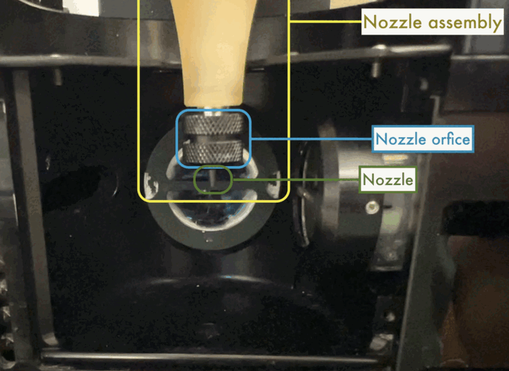
A picture with the nozzle installed. Note the
- Nozzle Assembly
- Nozzle Nut (Orifice)
- Nozzle
- Use the Nozzle Nut to install the Nozzle
- Make sure there is an undamaged O-Ring neslted in the Nozzle Nut orifice
asset Nozzle Nut O-ring
Undamaged Oring installed in the nozzle lock ring. The oring part number is ???
- Make sure the Nozzle is not obviously clogged:
- Use a 60ml Syringe filled with MilliQ water and fitted with an Acrodisc 0.2um Syringe Filter
- Place the Nozzle so that the wider end is around the outflow of the Acrodisc filter, and press lightly on the Syringe.
- Water should be ejected from the Nozzle Tip in a straight stream.
- If you cannot get a clear stream, try multiple light pressses on the Syringe plunger
asset “Unclogged Nozzle”
The stream should look like this when using the 60ml syringe to check for clogs
asset Clogged Nozzle
Our analysts are too
dishonestskilled to have photographic evidence of instrument malfunctions.- If the Stream comes out at an angle, attempt this flushing by reversing the Nozzle so that the tip is fitted into the outflow of the Acrodisc Filter. BE CAREFULE
- If Flushing in reverse does not work, Sonicate the Nozzle.
asset Sonnication Procedure
For stubborn clogs, try sonication. The nozzle inside the protective plastic lid, inside of the sonicator.
- Place the nozzle in a plastic lid (see example) to protect it from the bare metal of the sonicator
- Sonicate in MilliQ water for 15 minutes
- Attempt Syringe purges again
- If still clogged, soak Nozzle in 70% Ethanol for 30 minutes and repeat flushes and sonication
- Place Nozzle inside Nozzle Nut and install on Nozzle Assembly
PURGE vacuum won’t hold nozzle in place
(Applies to next step)
Using the vacuum pulled by PURGE will not hold the Nozzle aloft. Always support the nozzle manually or with the Nozzle Nut.- It may help to turn on PURGE on the Regulator Tower to open the Waste Valve and create a vacuum on the Nozzle Assembly to hold the Nozzle steady.
- After Nozzle has been installed, turn off PURGE if used.
- It may help to turn on PURGE on the Regulator Tower to open the Waste Valve and create a vacuum on the Nozzle Assembly to hold the Nozzle steady.
Hook-Up Sheath Fluid Canister to InFlux
Note
The Waste Pipe is plumbed to the Waste Tank via a piece of tubing that runs out of the rear/center of the Sort Chamber. Always inspect that tubing visually before starting the Sheath stream to ensure it has no holes or tears.
asset “InFlux sheath tank plumbed to instrument”
The InFlux sheath tank installed on the instrument with the inline filter and scale.
- Connect InFlux Sheath Line (clear)
asset “Sterivex installed”
Sterivex installed in sheath line and labeled with install date.
- Install a new 0.2um Sterivex In-line Filter
- Label the filter with a sharpie. Use clear tape to keep the ink from rubbing off.
- Connect InFlux Air Line (blue)
asset “Sheath tank”
“The sheath tank up close with valves and attachments.”
- Loosen Pressure Valve
- Optional Filter Sheath Fluid
asset “Sheath tank filtration”
Use the adapter to filter from one sheath tank into another.
- Disconnect 0.2um Sterivex In-line Filter at the outlet leading to the InFlux
- Get a clean Sheath Fluid Tank
- Connect Sheath Fluid Tank Fluid Intake Adapter filter Sheath Fluid from the original Tank to the clean one using the 0.2um Sterivex
- Loosen Pressure Valve on New Sheath Tank
- Purge and Fill Sheath Line
asset “Regulator tower PSI knobs”
“Knobs control air valve regulators inside the instrument (can also display a picture of a regulator?)”
- Working on the Air Regulator Knobs on the Right Side of the Instrument
- Use the Sheath Knob on the Right side of the instrument to set the Sheath PSI to 10.0. Starting with a psi lower than that may not overcome the Sterivex filter.
- On the Sheath Tank, Slowly tighten the Pressure Release valve on the
- You may need to wiggle the lid of the Tank to get the O-Ring to settle and seal the container
- And by wiggle I mean pull up while holding the tank down and twisting the lid handle.
- This is done to gently fill the 0.2um Sterivex In-line Filter so that it doesn’t have air bubbles
- Optional (If Filtering Sheath Fluid):
- Filter the Sheath Fluid from the Original Sheath Tank to the New Sheath Tank
- Transfer the Sheath Line and Sterivex to the New Sheath Tank.
- Disconnect the Fluid Intake Adapter from the Sterivex and the New Sheath Tank
- Connect the Sheath Fluid Outlet to the New Sheath Tank
- Connect the 0.2um Sterivex to the Sheath Line leading to the instrument
- Once Sheath Tank is pressurized, increase the Sheath PSI to 15.0 using the Knob on the Regulator Tower
RINSE sends sheath directly to waste
- Using the RINSE button opens the waste line valve that leads from the top of the nozzle assembly Y-Connector to the waste tank.
- At 15psi, this can drain an entire sheath tank in less than 40 minutes.
- Sheath will also flow into the nozzle assembly (and therefore sample line)
asset “Sheath Control Buttons and valves”
Sheath control buttons and sheath valves on top of regulator tower. Note that:
- RUN must be turned off before any other button can be activated
- Press the RINSE button on the Regulator Tower to open the Sheath and Waste valves.
- Stop the Rinse when Sheath Fluid reaches the Y-Connector affixed to the upper right corner of the Nozzle Assembly
- See figure below
Purge Nozzle and Nozzle Assembly
asset “Upclose nozzle assembly flowpath”
The flow path for sheath fluid entering the middle assembly
- Ensure that Nozzle has been installed (see section Install Nozzle)
- Place the Drain below the Nozzle Assembly, the peg on the bottom of the Drain should fit into the hole leading to the Sort Chamber
asset “Drain installed”
Notice the drain is flush with the bottom of the laser chamber.
- Place the glass Spoon on the Drain such that the Nozzle is inside the spoon
asset “Spoon on drain with appropriate sheath fluid”
The spoon resting on the drain and filled with sheath fluid from the 0.2um syringe.
- Fill the Spoon with 0.2um filtered Sheath Fluid from the Syringe with the 0.2um Acrodisc Filter
- The Water level should be high enough to immerse the Nozzle Tip, but below the level where it would cover the Nozzle Nut in fluid
- Press PURGE to open the Waste Valve leading from the Sheath Fluid Y-Connector to the Waste Canister
- Forget to fill a syringe? Use the sheath tank (up through the sterivex) to fill a syringe. CAUTION: lower the sheath tank psi before disconnecting the sterivex!
- This will fill the Nozzle Assembly by drawing water from the Spoon
asset “Sheath being drawn into nozzle assembly”
The nozzle assembly flow path will begin to fill.
- Be sure that the OVERRIDE Button next to the Sample Cradle is not pressed.
- Do not let the sheath water level in the Spoon drop below the Nozzle Tip.
- Continue Purging until Sheath Fluid drawn into the Nozzle Tip and up through the Nozzle Assembly reaches the Y-Connector at the top of the Nozzle Assembly.
asset “Y Connector air bubble”
Air being drawn into the waste tank while PURGE is active.
- You should see the air bubble flow out of the Y-Connector and into the Waste Line at the top of the Y-Connector.
- Briefly press the RINSE Button to open the Sheath Valve and Waste Valve to chase bubbles out of the Y-Connector
- Press the PURGE Button to open the Waste Valve and close the Sheath Valve
- Press the PULSE Button on the Regulator Tower to open and close the Sheath Valve several times in quick succession.
- Air Bubbles from the Nozzle should be loosened and begin to travel up through the Nozzle Assembly. Continue with PURGE until all bubbles are removed from the Nozzle Assembly.
- There will often be a stubborn bubble that forms in the 45 degree angle in the nozzle flow path
asset “Air bubble in flow path”
It is very likely you will see this bubble.
asset “Acceptable air bubble”
If the air bubble is this small, then it will naturally dissolve into the sheath over time.
Purge Troubleshooting
If you are having trouble getting the air out of the nozzle assembly:
- Be sure that the OVERRIDE Button next to the Sample Cradle is not pressed. This Button forces the Sample Valve Open. Normally the Sample Valve only opens if RUN is pressed.
- Check for bubbles
From inFlux Cell Sorter Operator Manual:Ensure there are no bubbles in the system by closing the SHEATH Valve (Turn off RINSE and RUN).
If the stream snaps off quickly (<1 second) then there are no bubbles and you may proceed.
If the stream takes 10-30 seconds to stop, there are bubbles. Continue debubbling procedures. - Press the RUN Button on the Regulator Tower to close the Waste Valve and open the Sheath Valve.
- Proceed directly to the next step.
Check for leaks
asset “Instrument picture with common leak points”
A few common points of failure.
Check for leaks from:
- Nozzle Assembly:
- Y-Connector (all three joints)
- PEEK Fitting from Y-Connector to Nozzle Assembly
- Nozzle Lockring
- Sample Line (with BACKFLUSH on)
- Both flow meters. Notice that on either end of the flow meter there are two PEEK fittings from which it can leak.
- Sample Air Filter
- The air filter outflow is a Luer slip tip fitted into a 1/16" Barb LuerLok Female fitting.
- PEEK Fitting connecting the sample air filter to the T-Joint on the sample line.